I was recently asked about the idea of an app for creating score videos: videos showing musical notation in sync with audio. I don’t think a score video app is a bad idea, but there are so many styles of score videos (some include performance footage, text annotations, or colorful backgrounds) that by the time you ship an app, you’ll have reimplemented a huge chunk of DaVinci Resolve, at which point you’ll be competing with the free version of an app that’s used in Hollywood film production. So, I thought I’d share how I make score videos like the ones on my YouTube channel. I use Resolve on macOS, but hopefully some of this applies to other apps.
There are essentially three parts to a score video:
- The start, where the playhead moves a bit to the right of the first notes while the score stays still
- The middle, where the playhead stays still while the score scrolls to the left (this is usually the longest part by far)
- The end, where the playhead moves to the last notes while the score again stays still
In all three steps, the location of the playhead is in a resolution-independent coordinate system, but the locations of notes in a score are in a resolution-dependent coordinate system defined by pixels. So, the main challenge in making score videos is converting pixel locations of notes to what a video app expects.
Convert the Score to an Image File
The first thing we need for a score video is a raster image file (like a PNG) of a score, ideally as one continuous system. Creating this can be tricky. I use LilyPond to notate music, and LilyPond can output a one-system PNG directly:
touch score.ly # Create an empty score.ly if one does not exist.
lilypond \
  --loglevel=ERROR \
  --output=single-system-score \
  --png \
  --define-default=resolution=300 \
  - <<< '
	  \include "score.ly"
	  \paper {
	    page-breaking = #ly:one-line-auto-height-breaking
	    top-system-spacing = #f
	    indent = 0
	    left-margin = 1\in
	  }
'(Note that this will produce no output if score.ly is empty. If you use LilyPond, try running this on one of your own scores, or add \relative { c' d e f g a b c } to score.ly.)
If you use a notation app like Dorico or Sibelius, you may be able to output a (very wide) PDF containing one system, and then you can convert the PDF to a raster image. I almost always use poppler to rasterize PDFs (the images in my shop are all from poppler). On macOS, you can install poppler using Homebrew—
brew install poppler—and then convert a PDF to a 300-dpi PNG using, for example:
pdftoppm -r 300 -png ⟨input-pdf-file⟩ ⟨output-filename⟩If all you have is a paginated PDF (from IMSLP, for example), you have your work cut out for you. You’ll probably need to script poppler to output every system to separate image files, and then you’ll (somehow) need to stitch those into a single image file using something like ImageMagick or perhaps Photoshop’s Photomerge feature. I’ve never done any of this, but it’s safe to say that it’s a lot of work.
Load the Image
In theory, we can import the score image into DaVinci Resolve (or another video app) and sync audio to it. However, Resolve on macOS uses the Metal graphics API to load images into what are called textures, and Metal limits the width of textures to (usually) 16,384 pixels (page 8, “Maximum 2D texture width and height”). Importing a score image won’t work if the image is too wide for Metal, and score images tend to be much wider than Metal’s limit (I found all this out on the Blackmagic forum).
Rather than import the image directly, we’ll use a Fusion composition. Since we’ll also use Fusion to draw the playhead, we’ll add that to the composition while we’re at it:

This composition consists of two sequences of nodes.
- The top sequence (in blue) manages the playhead. We’ll come back to this.
- The bottom sequence (in green) manages the score image. The Loader node displays an image at a particular file path, the Transform node named “ScoreTransform” scales and translates the image, and the Crop node makes the image the same size as the project timeline.
The playhead is drawn on top of the score using a Merge node with an Apply Mode of Darken, and the MediaOut node is boilerplate.
We could set the ScoreTransform’s Size property and keyframe its Center point to scroll an image in sync with audio, but there are several drawbacks to this approach:
- Keyframing the Center X coordinate alone is impossible. You can only keyframe the Center point, which means that if you animate a score and later need to adjust its vertical position, you must update Center Y coordinates of every keyframe.
- We have to use Fusion’s keyframe editor rather than Resolve’s more intuitive Edit view.
- It’s not easy to set Center X coordinates precisely.
- How a Transform translates an image is determined by its Center point and Size. If you keyframe the Center point and later adjust the Size, every Center point keyframe must be updated.
Resolve is an enormous app, and I’m a novice at best, but my solution to the first problem is to add extra controls to the Transform nodes and set Center points using expressions, my solution to the second problem is to create a Fusion group and use that in the Edit view, and my solution to the last two problems is to do a bunch of math.
Scale the Score
Here’s how the ScoreTransform is set up:
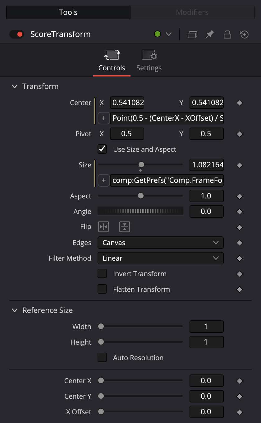
Don’t worry about the expressions used for the Center point and Size just yet, but do notice the three extra controls at the bottom: Center X, Center Y, and X Offset. To add a control to the Transform node, Control-click it, and then choose Edit Controls from the menu that appears. Here are the settings for the Center X control:
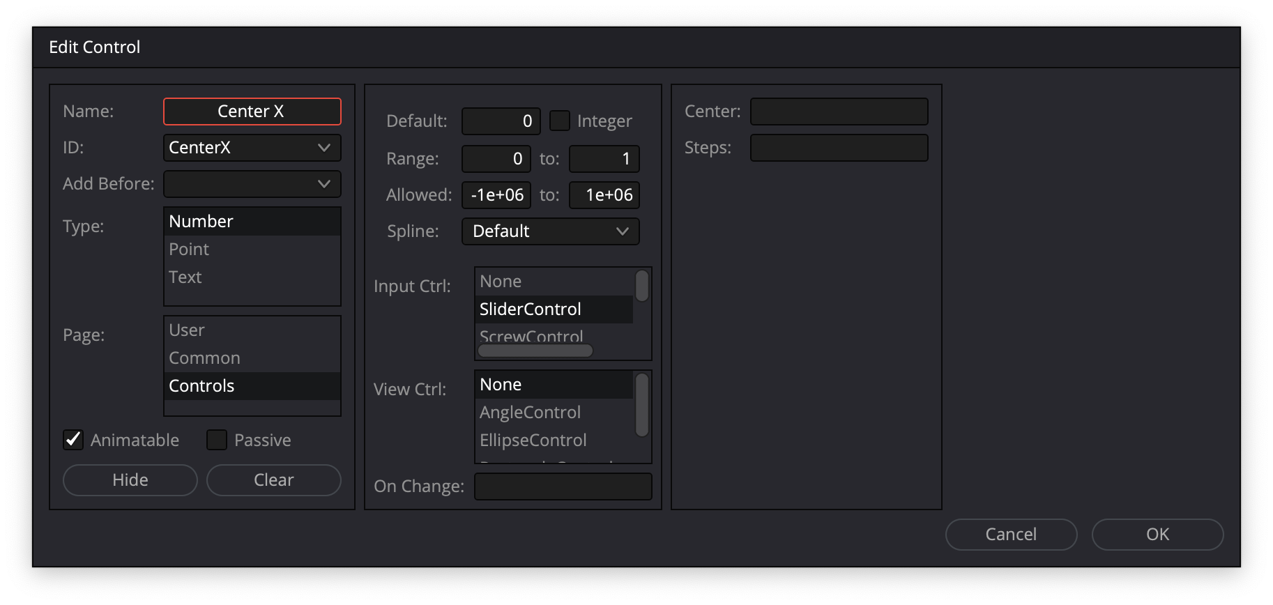
Note the ID: CenterX. The two other controls are the same except for names and IDs (CenterY and XOffset).
We’ll use the values of these three new controls in expressions. To make this more concrete, we can load the image of the score of my piano piece Kyrie Eleison:

When we load this image using the ScoreTransform’s default Center point and Size, we’ll see that height of the image is less than the height of the composition:
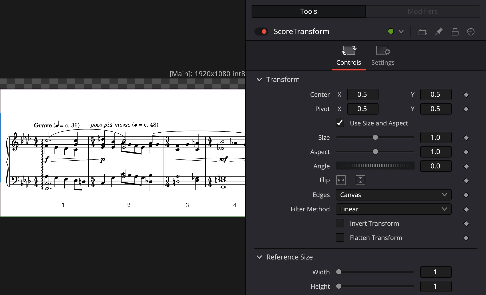
The image is 998 pixels high, and the composition is 1080 pixels high, so scaling the image by a factor of 1080/998 will make the image 1080 pixels high. All well and good, but if the image height changes for some reason, or if we switch to a vertical resolution, we’ll need to change the scale factor. We can make Resolve do this for us by using an expression to calculate Size. To do this, Control-click the control name “Size” in the Inspector, choose Expression from the menu that appears, and enter:
comp:GetPrefs("Comp.FrameFormat.Height") / ScoreTransform.Input.Height(This is an excellent reference for Fusion expressions.)
Using that expression makes the image the same height as the composition, but now it’s too low and too far to the left:
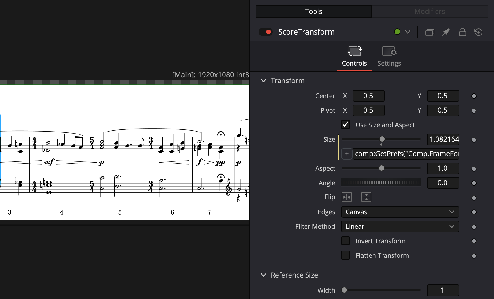
This is because Transform nodes divide their Center coordinate by Size to calculate a translation. We can use another expression for the Center coordinate to work around this:
Point(CenterX, CenterY) * SizeSet both Center X and Center Y to 0.5, and the score should appear as expected:
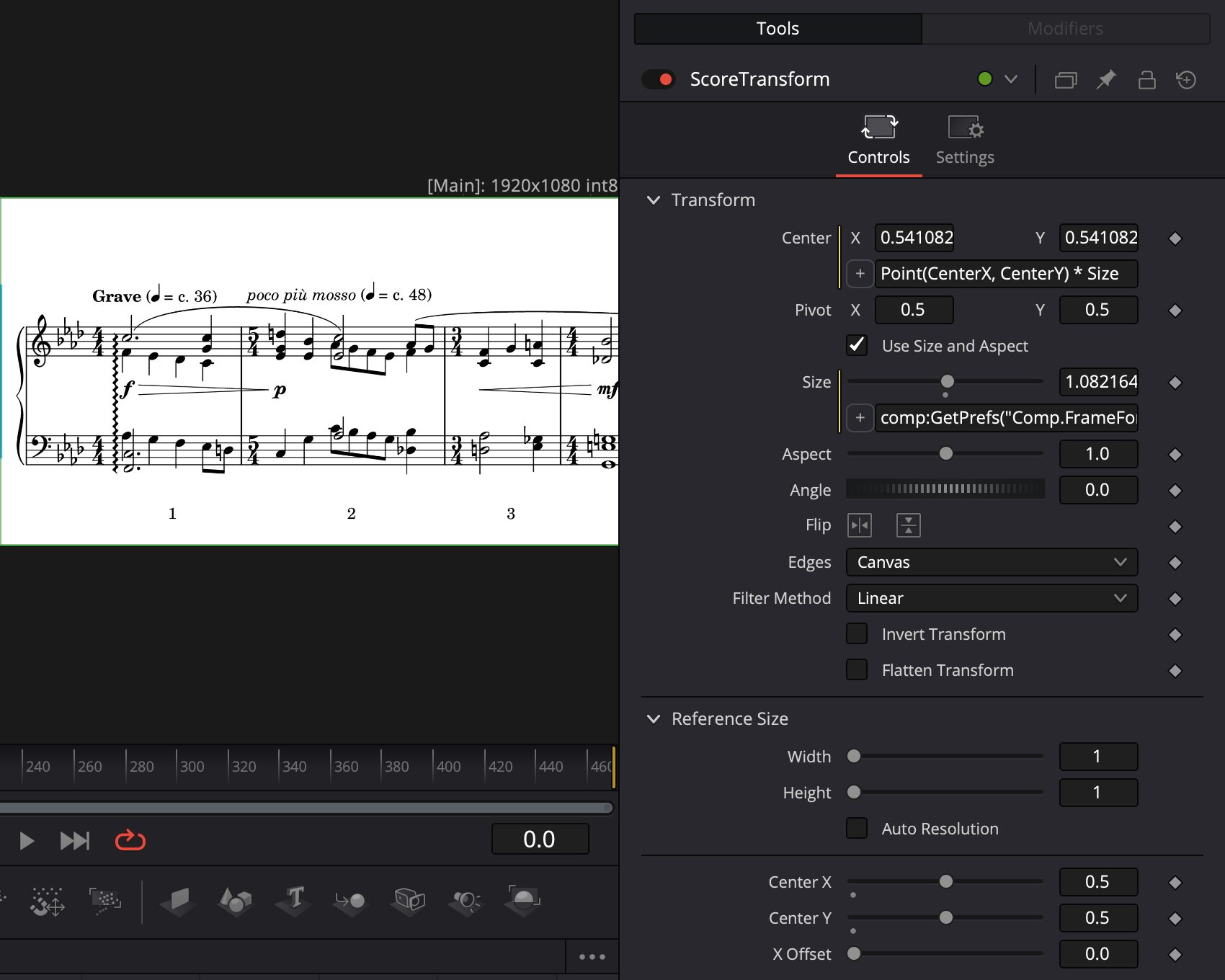
(Having the score the same height as the composition is usually what one wants, but if a score has, for example, overly wide margins, you can multiply the Size by a fudge factor to eliminate the margins.)
Vertically Shift the Score
After all that, the score still looks a bit too low. We can adjust the vertical position of the score by changing the Center Y coordinate. It may seem like overkill, but we can set things up so that Center Y is in pixels. If we leave all the other properties of the ScoreTransform node alone, the y-coordinate of the Center point tells us where the transformed image is relative to the bottom edge of the composition:
| When the y-coordinate of the Center point is | the transformed image |
|---|---|
| 0.5 | has its bottom edge flush with the bottom edge of the composition |
| 1 | has its bottom edge in the middle of the composition (so the top half of the image isn’t visible) |
This means we need to map a pixel’s y-coordinate to:
- 0.5 when the pixel’s y-coordinate is 0
- 1 when the pixel’s y-coordinate is half the image height
This does the trick:
The Details
The equation of a line through points (y1, z1) and (y2, z2) can be written as:
Plugging in and , we get:
(Apologies for WordPress’ buggy equation alignment.)
This makes the Center coordinate expression:
Point(CenterX, 0.5 + CenterY / ScoreTransform.Input.Height) * SizeAnd here’s what the score looks like 60 pixels higher:
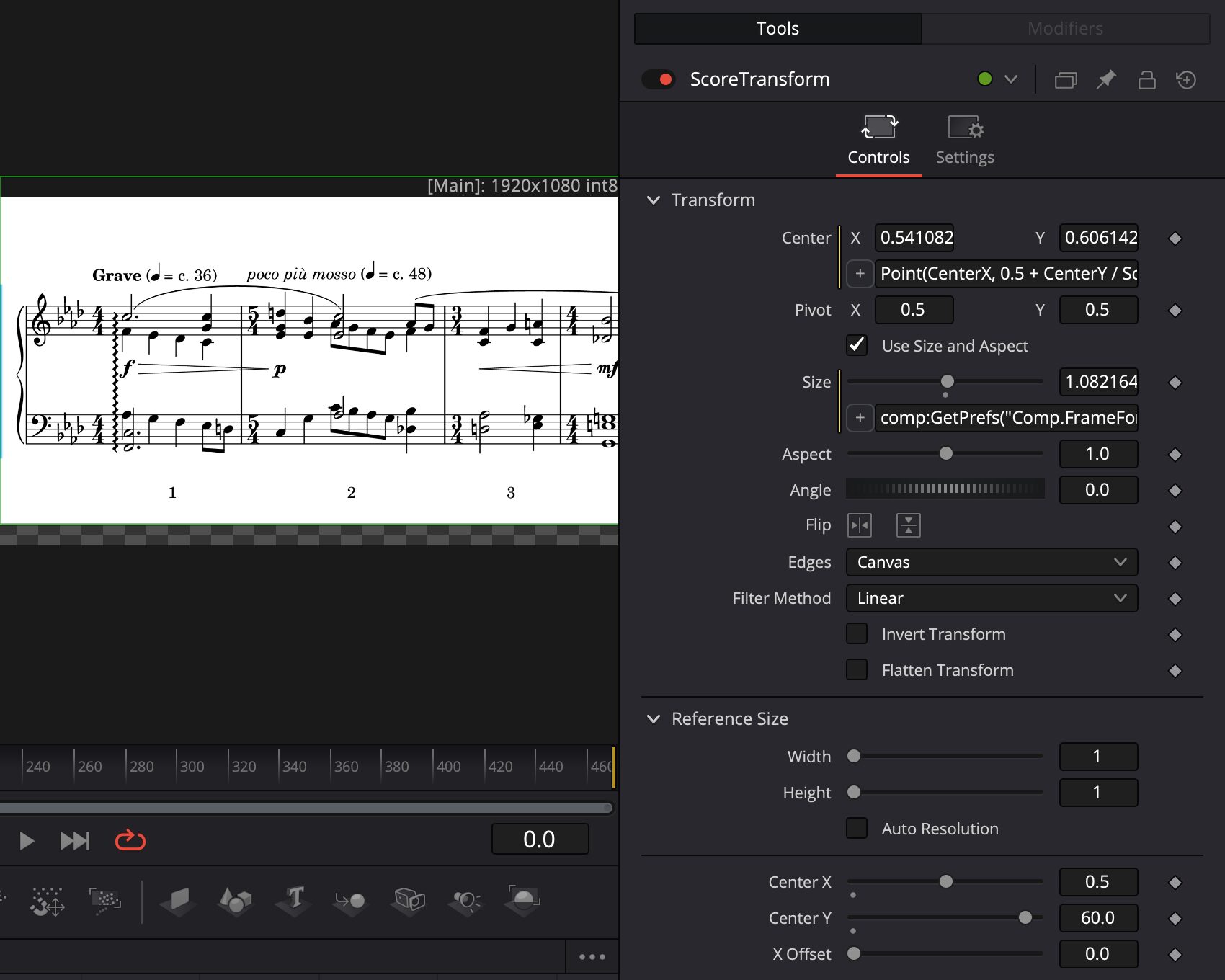
(Don’t worry about the checkerboard background that’s now visible. We can add a white background using a Solid Color generator effect so that the entire composition is filled in.)
Crop the Score
By default, the Crop node crops the score to be the same size as the timeline, but this is a happy accident. If we switch to a vertical orientation, the score will be cropped to the wrong size. We can use expressions to ensure that the score is always cropped to the size of the timeline:
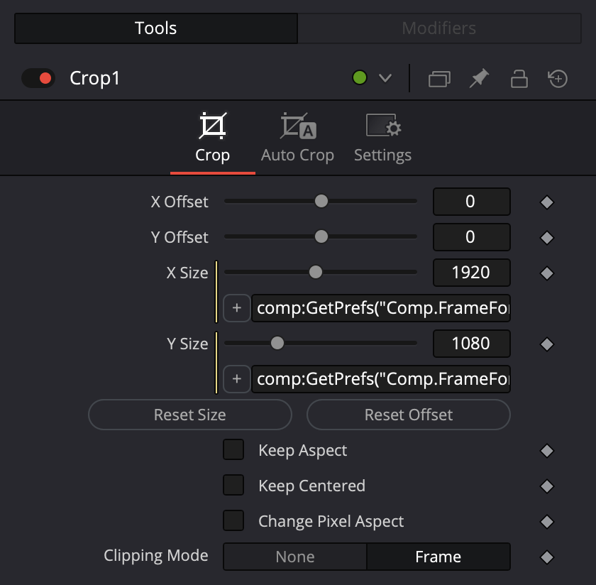
The expression for X Size is:
comp:GetPrefs("Comp.FrameFormat.Width")And the expression for Y Size is:
comp:GetPrefs("Comp.FrameFormat.Height")Draw the Playhead
Here’s the Fusion composition again:
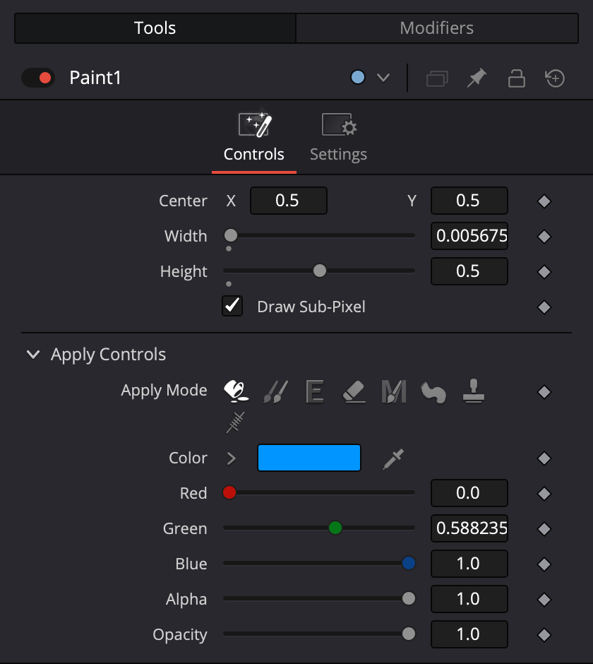
Now let’s focus on the top (blue) sequence. The Paint node draws the playhead as a thin rectangle, the GaussianBlur node gives the rectangle a softer appearance, and the Transform node named “PlayheadTransform” moves the playhead. (The transparent Background is required by the Paint node.)
Here’s how the rectangle in the Paint node is set up:
And here’s the PlayheadTransform, with default settings and the same three extra controls as the ScoreTransform:
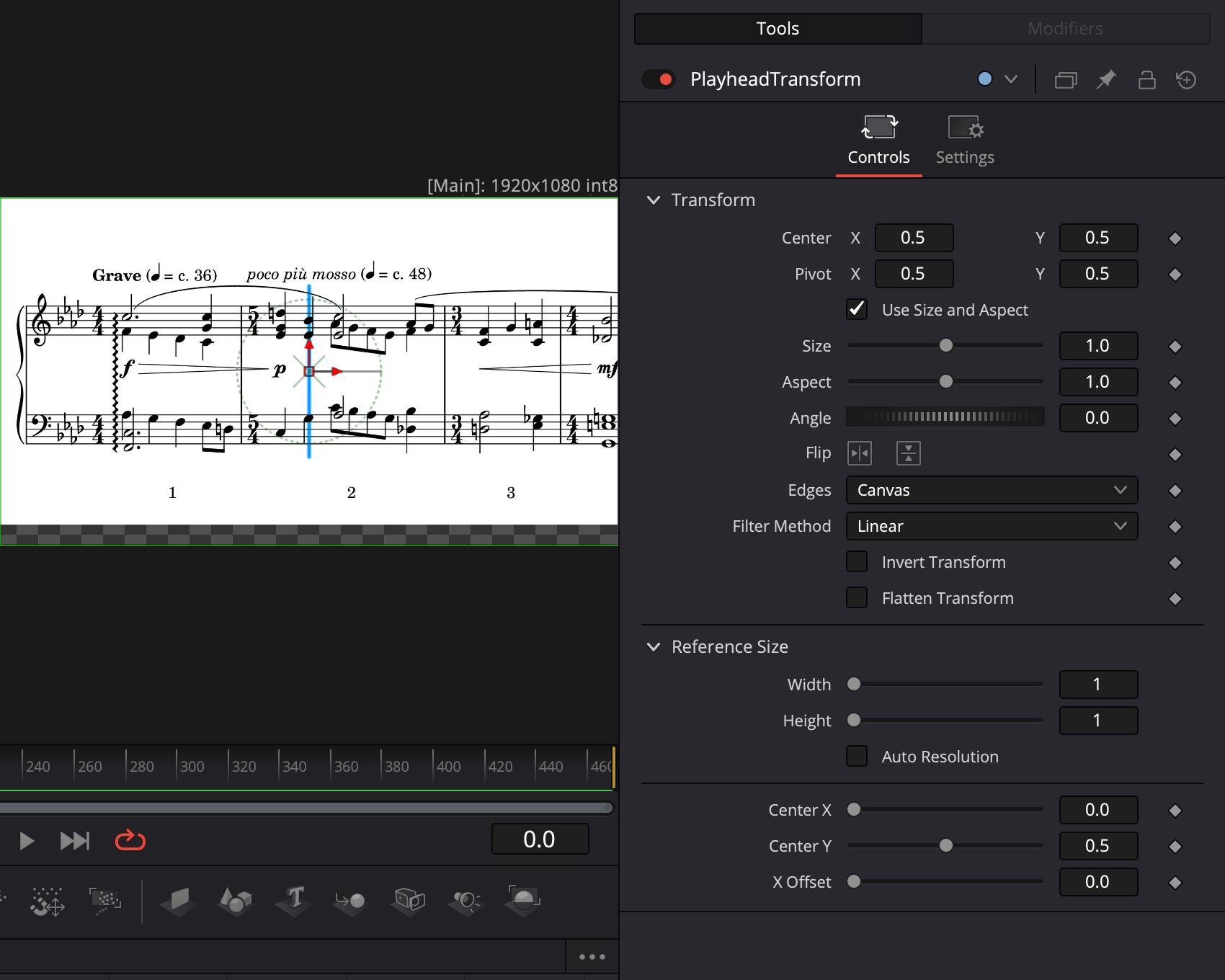
With a Center point of , the playhead is in the middle of the composition, on top of some notes. In pixels, the x-coordinate of these notes is about 885. (To quickly find pixel coordinates, I use Pixelmator Pro’s Info Bar: View > Show Info Bar. If you use Photoshop, you can use the Info panel.) We can take the guesswork out of aligning the playhead to notes by treating the Center X control as pixels, and then using the values of the Center X and Center Y controls in an expression for the Center point.
The Center point’s x-coordinate is 0 when the playhead is at the left edge of the composition, and 1 when the playhead is at the right edge. If we didn’t scale the score to make it the same height as the composition, we could use
Point(
  CenterX / comp:GetPrefs("Comp.FrameFormat.Width"),
  CenterY
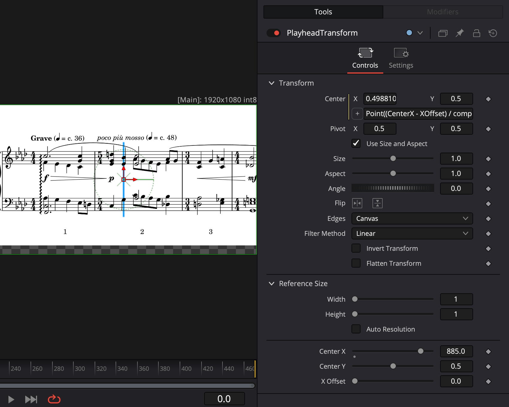
)for the Center point expression (which you can check by varying Center X between 0 and 1920). However, we did scale the score, so we also have to apply that scale factor here. While we’re at it, we’ll also include the X Offset in the expression (but we won’t use it yet):
Point(
  (CenterX - XOffset) / comp:GetPrefs("Comp.FrameFormat.Width") *
    ScoreTransform.Size,
  CenterY
)Now when Center X is 885, the playhead is on top of the notes at pixel position 885:
Scroll the Score
We’ve almost assembled enough machinery to starting scrolling the score under the playhead. Here’s where things stand with the ScoreTransform:
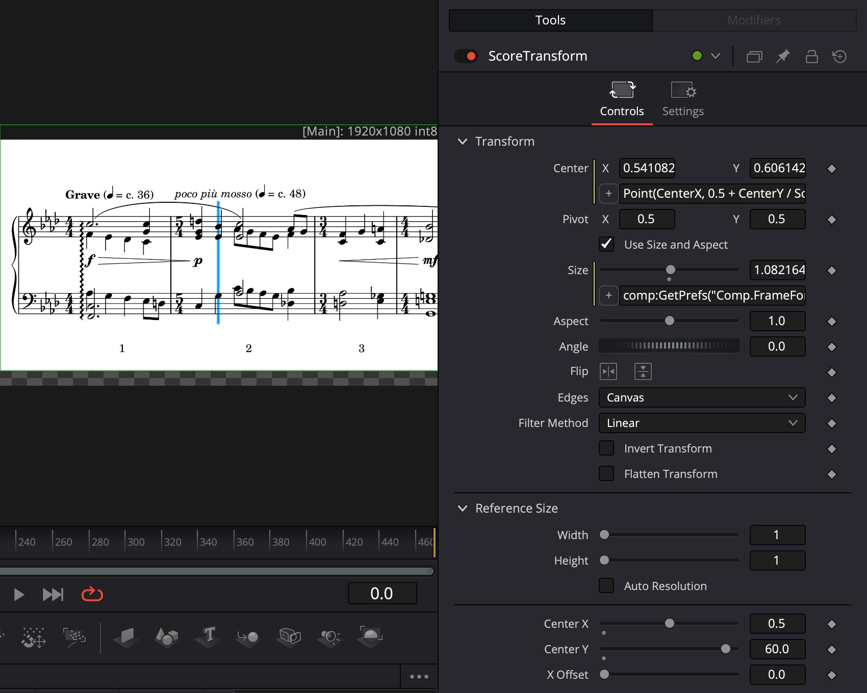
We were able to set up the custom Center X control of the PlayheadTransform to correspond to pixels in the score image, and it would be great to do the same thing in the ScoreTransform.
If we leave all the other properties of the ScoreTransform alone, the x-coordinate of the Center point tells us where the transformed image is relative to the left edge of the composition:
| When the x-coordinate of the Center point is | the transformed image |
|---|---|
| 0.5 | has its left edge flush with the left edge of the composition |
| 0 | is centered at the left edge of the composition (so the left half of the image isn’t visible) |
| –0.5 | has its right edge flush with the left edge of the composition (so none of the image is visible because it’s outside the composition) |
This means we need to map a pixel’s x-coordinate to:
- 0.5 when the pixel’s x-coordinate is 0
- 0 when the pixel’s x-coordinate is half the image width
- –0.5 when the pixel’s x-coordinate is equal to the image width
This does the trick:
Including the X Offset (which we’ll need soon), the final expression is:
Point(
  0.5 - (CenterX - XOffset) / ScoreTransform.Input.Width,
  0.5 + CenterY / ScoreTransform.Input.Height
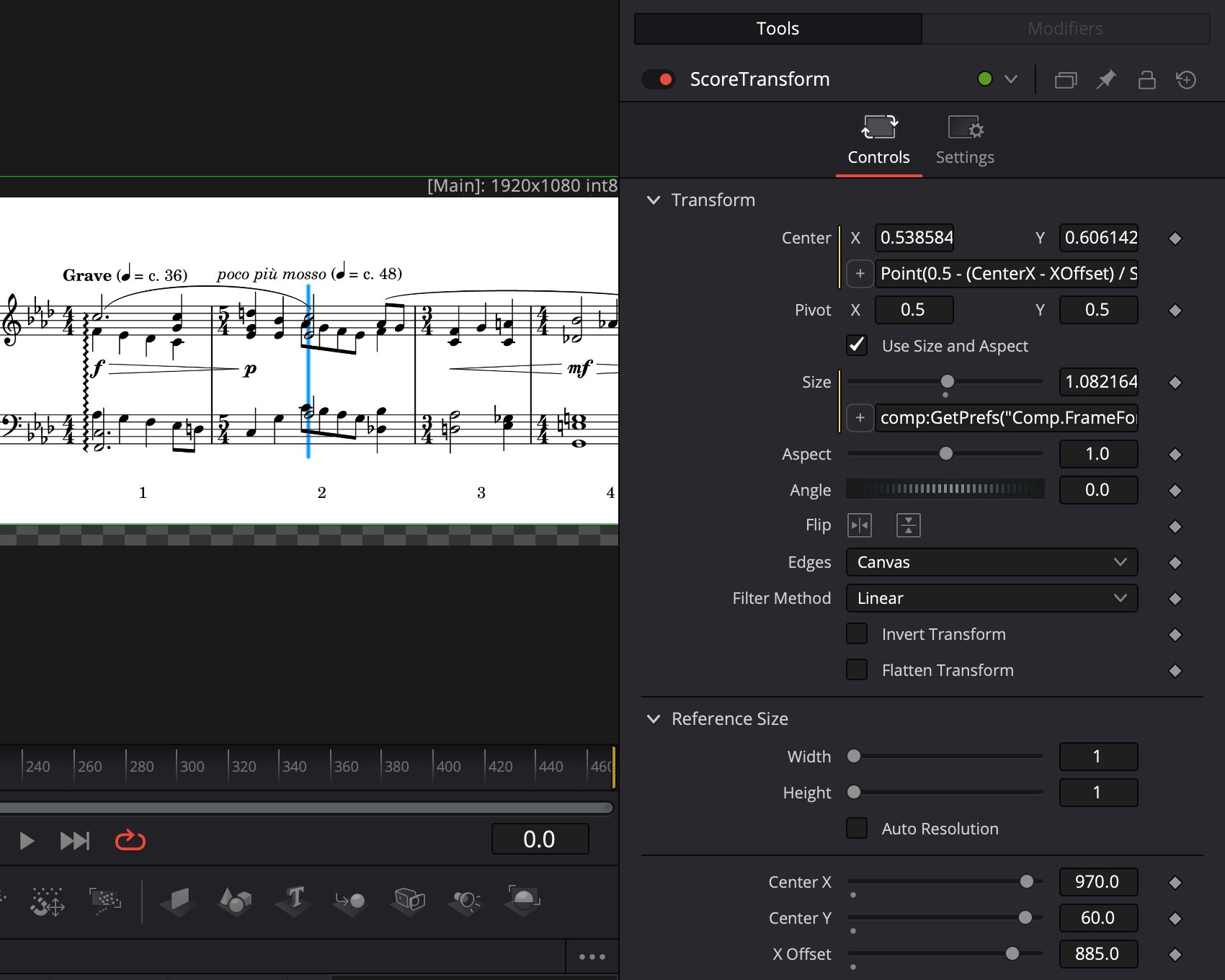
) * SizeThe collection of notes after the playhead has an x-coordinate of about 970. Ideally, we’d like to set the Center X control to 970 and have the notes at 970 appear under the playhead, but if we set the Center X control to 970, those notes end up at the left edge of the composition. This is because we need to take into account the position of the playhead when scrolling the score, and we have an X Offset control to do just that. Setting the X Offset to 885 (the same value as the Center X of the PlayheadTransform) scrolls the score as we expect:
Save the Composition as a Group
To save the Fusion composition as a reusable group, select all the nodes in the composition, Control-click the selected nodes, and then choose Macro > Create Macro to show the Macro Editor. Choose the “Group” radio button to the left of the macro name field (containing “MacroTool1” by default). By saving the composition as a group instead of a macro, we’ll be able to access individual nodes of the composition later.
The Macro Editor may seem overwhelming, but you typically only need to choose the controls that will be visible by selecting checkboxes in the Export column. (You can also change the control names that appear in the Edit view by editing fields in the Name column.) Here are the controls I chose, as shown in the Edit view:
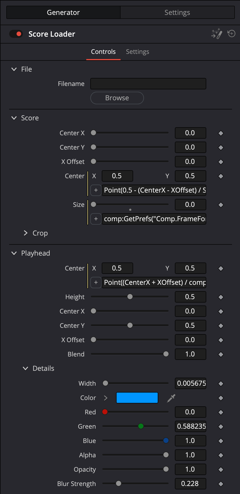
To save the macro, click the Macro Editor Option button in the upper righthand corner of the Editor (looks like ⋯), and then choose Save or Save As from the menu that appears. The default folder in which Fusion saves macros is not the folder we want. Save the macro in the Templates/Edit/Generators folder, not the Macros folder.
If you want to change the group later, you can edit it in the Fusion view: in Resolve’s menu, choose Fusion > Macro Editor, click the Macro Editor Option button, and then choose Open from the menu that appears.
Quit and restart Resolve. The group should appear in the Edit view as a Generator effect, and we can finally load a score image into a timeline.
Finishing Up
At this point, we can use the Fusion group in Resolve’s Edit view to keyframe Center X controls in sync with audio. The vast majority of the work will be keyframing the ScoreTransform’s Center X control.
There are two remaining items: vertically positioning and setting the height of the playhead, and what to do with the playhead at the end of the score.
In theory, it should possible to calculate the playhead’s vertical position and height based on the pixel positions of the staff, but I usually eyeball this.
At the end of the score, we’ll want to set the playhead’s Center X to pixel locations in the score, but the score has now been scrolled by quite a bit. This is where we can use the PlayheadTransform’s X Offset. By setting the PlayheadTransform’s X Offset and Center X using the ScoreTransform’s Center X in the same keyframe, the playhead will appear stationary, and then we can set the PlayheadTransform’s Center X to pixel locations as needed.